Tuesday, February 23, 2010

A fun distraction - Topographic Contour Shader


While working on the normal re-calculation for my spherical deformer vertex shader, I got distracted by an idea I had. Thinking about Avatar, and virtually any other movie with high tech 3D displays of terrain, I thought it would be cool to develop a fragment shader to draw the object as stacked countour lines, like those found on a topo map.

I developed a simple version using modulus of one spacial dimension, but the results weren't quite the "wireframe" look I was going for. With the help of this thread I learned about smoothstep() and was able to get exactly what I was going for.

Wednesday, February 17, 2010

GLSL mesh deformer in spherical coordinates - part 3


Getting closer on properly re-calculating the normals after radial deformation in GLSL. To recap, I built a radial deformer like a jellyfish or spore type form when applied to a sphere. While displacing vertices is fairly easy, re-calculating the normals has been tricky. The visual appearance is getting very close to the phong-shaded deformed sphere I'm shooting for.. However it still isn't perfect.

Since last time, here are the advancements that have brought me closer to the goal:

- Don't normalize any vectors in Spherical coordinates. Since they're measuring angles & radius, a normalization doesn't make sense. This was causing all kinds of crazy problems.
- Cartesian-to-spherical function modified to check for bounds of asin and check hemisphere for atan. Holes in mesh have been fixed.
- Now using the proper built in GLSL matrix functionality.

The current method for calculating normals for deformed vertex is as follows:

- Convert incoming vertex to spherical
- Displace this vertex by 3 component (r, theta, phi) deform function
- Find unit tangent vector U (in Cartesian coords)
- Find binormal vector V (in Cartesian coords)
- Convert these to spherical coords
- Find Jacobian matrix for current vertex (in Spherical coords)
- Multiply U by Jacobian to get U' (transformed unit tangent vector)
- Multiply V by Jacobian to get V' (transformed binormal vector)
- Convert these back into cartesian
- Transformed normal, in Cartesian is normalize(U'X V')


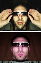
With this method, the shading/highlights still don't look perfect when deformed. I'm almost positive that the culprit is my Jacobian matrix, since when the deformation amount is zero, the object looks perfect: In other words, when the deformation is zero, the whole process of renormalization is still happening, but just coming out identical to the inputs. I'm wondering if my method of simply replacing x,y,z with r,t,p in the Jacobian is legit.. Maybe I have to convert the functions somehow. More reading to come..

Wednesday, February 10, 2010

GLSL vertex deformer part 2


I began to implement the second part of the GLSL mesh deformer. This part was all about recalculating the surface normals after procedurally moving the vertices of the model. Following the directions provided at this link I was able to perform the steps to calculate a Jacobian matrix based on the original deformation forumla. Using this matrix I was able to correct the surface normals post-deformation.. sort of.

Since this deformation was a radial displacement, I was operating in the polar coordinate system. So before performing the partial derivatives to create the Jacobian matrix, I had to convert some things to polar coordinates. The steps were as follows:

- Convert the vertex position into polar
- Create the Binormal and tangent vectors as described in this link
- Convert the binormal and tangent vectors to polar coordinates
- Convert the incoming surface normal to polar
- Plug all the data into the hard coded Jacobian matrix
- Calculate the new surface normal
- Convert the new surface normal back into cartesian 3 space

With this method, I think I got very close to the desired effect of perfectly deformed surface normals to go along with the deformed mesh. However visually there are still some problems.

I believe the cartesian-to-polar function has some discontinuities that result in holes in the mesh. Also the shading looks off in some way, possibly related to the double coordinate system translation being slightly off. But its getting closer!


Here's the vertex shader as it stands..


const float TWO_PI=6.28318531;
const float PI=3.14159265;
const float HALF_PI=1.57079633;

varying vec4 screenPos, worldPos;

varying vec3 normal, lightDir, halfVector;
varying vec4 diffuse, ambient;

varying float radius,redShift,greenShift,blueShift;

uniform float time;
uniform float displaceAmount1;
uniform float displaceAmount2;

uniform float frequency1;
uniform float frequency2;

varying vec4 eyePosition;
varying vec3 diffuseColor;
varying vec3 specularColor;
varying vec3 emissiveColor;
varying vec3 ambientColor;
varying float shininess;
//varying vec3 normal;

vec3 va;//={0,0,1};
vec3 vb;//={0,1,0};

vec3 renormalizeA;
vec3 renormalizeB;
vec3 renormalizeC;


vec3 vertexSpherical;

float d0;
float d1;
float d2;
float x,y,z;
// float theta,phi,r;

vec4 displacedPoint;

float tri(float phase)
{
float ramppoint;
phase =mod(phase,TWO_PI);
ramppoint=mod(phase,HALF_PI)/(HALF_PI);
if(phase>=0.0 && phase else if(phase>=HALF_PI && phase else if(phase>=PI && phase<(HALF_PI*3.0)) return(-ramppoint);
else if(phase>=(HALF_PI*3.0) && phase<=TWO_PI) return(-1.+ramppoint);
else return(1.0);
}

vec3 sphericalToCartesian( vec3 sphericalCoord)
{
vec3 o;
o.x=sphericalCoord[0]*sin(sphericalCoord[1])*cos(sphericalCoord[2]);
o.y=sphericalCoord[0]*sin(sphericalCoord[1])*sin(sphericalCoord[2]);
o.z=sphericalCoord[0]*cos(sphericalCoord[1]);

return o;

}
vec3 cartesianToSpherical( vec3 cartesianCoord)
{
vec3 o;

float S;

o[0]=length(cartesianCoord);

S=length(cartesianCoord.xy);

o[1]=acos(cartesianCoord.z / o[0]);


//o[2]=atan(cartesianCoord.y/cartesianCoord.x);
if(cartesianCoord.x>=0.0) o[2]=asin(cartesianCoord.y/S);
else o[2]=PI-asin(cartesianCoord.y/S);


return o;

}


float f_r(float rOriginal)
{

return rOriginal+cos(vertexSpherical[1]*frequency1+time)*displaceAmount1 +cos(vertexSpherical[2]*frequency2+time)*displaceAmount2;

}

float f_theta(float thetaOriginal)
{

return thetaOriginal;

}

float f_phi(float phiOriginal)
{

return phiOriginal;

}


void main()
{

x=gl_Vertex[0];
y=gl_Vertex[1]; //flip flopped, so angular parts map to sides ("walls"), instead of along top
z=gl_Vertex[2];

vertexSpherical=cartesianToSpherical(gl_Vertex.xyz);


vec4 displaceVect;


vec4 Vertex=gl_Vertex;

vertexSpherical[0]=f_r(vertexSpherical[0]);
vertexSpherical[1]=f_theta(vertexSpherical[1]);
vertexSpherical[2]=f_phi(vertexSpherical[2]);

displacedPoint[0]=vertexSpherical[0]*sin(vertexSpherical[1])*cos(vertexSpherical[2]);
displacedPoint[1]=vertexSpherical[0]*sin(vertexSpherical[1])*sin(vertexSpherical[2]);
displacedPoint[2]=vertexSpherical[0]*cos(vertexSpherical[1]);
displacedPoint[3]=1.0;

Vertex=displacedPoint;

redShift=0.0;//abs(r);
greenShift=0.0;//abs(theta/6.0);
blueShift=0.0;//abs(phi/6.0);


worldPos=Vertex;
screenPos=gl_ModelViewProjectionMatrix * Vertex ;

gl_Position = screenPos;

eyePosition = gl_ModelViewMatrix * gl_Vertex;

normal = gl_Normal;//normalize(gl_Normal + normalize( gl_Normal-worldPos.xyz));


//Post-deform renormalization:

//Create a couple utility vectors:
va.x=0.0;
va.y=0.0;
va.z=1.0;

vb.x=0.0;
vb.y=1.0;
vb.z=0.0;

va=cartesianToSpherical(va);
vb=cartesianToSpherical(vb);
normal=cartesianToSpherical(normal);


//Generate tangent vector:
vec3 tangent, transformedTangent;
if(length(cross(normal,va))>length(cross(normal,vb))) { tangent=cross(normal,va);}
else { tangent = cross(normal,vb); }

//Generate binormal vector
vec3 binormal, transformedBinormal;
binormal=cross(normal, tangent);


//The Jacobian Matrix :
renormalizeA[0]=1.0;
renormalizeA[1]=-displaceAmount1*sin(frequency1*vertexSpherical[1]+time)*frequency1;
renormalizeA[2]=-displaceAmount2*sin(frequency2*vertexSpherical[2]+time)*frequency2;
renormalizeB[0]=0.0;
renormalizeB[1]=1.0;
renormalizeB[2]=0.0;
renormalizeC[0]=0.0;
renormalizeC[1]=0.0;
renormalizeC[2]=1.0;


transformedTangent.x=tangent.x*renormalizeA[0]+tangent.y*renormalizeA[1]+tangent.z*renormalizeA[2];
transformedTangent.y=tangent.x*renormalizeB[0]+tangent.y*renormalizeB[1]+tangent.z*renormalizeB[2];
transformedTangent.z=tangent.x*renormalizeC[0]+tangent.y*renormalizeC[1]+tangent.z*renormalizeC[2];

transformedBinormal.x=binormal.x*renormalizeA[0]+binormal.y*renormalizeA[1]+binormal.z*renormalizeA[2];
transformedBinormal.y=binormal.x*renormalizeB[0]+binormal.y*renormalizeB[1]+binormal.z*renormalizeB[2];
transformedBinormal.z=binormal.x*renormalizeC[0]+binormal.y*renormalizeC[1]+binormal.z*renormalizeC[2];


vec3 transformedNormal=normalize(cross(transformedTangent,transformedBinormal));

normal=sphericalToCartesian(transformedNormal);


normal = gl_NormalMatrix * normal;//gl_Normal;


diffuseColor = vec3(gl_FrontMaterial.diffuse);
specularColor = vec3(gl_FrontMaterial.specular);
emissiveColor = vec3(gl_FrontMaterial.emission);
ambientColor = vec3(gl_FrontMaterial.ambient);
shininess = gl_FrontMaterial.shininess;

}


Tuesday, February 9, 2010

Adventures in GLSL Shaders


I'm finally getting deeply into the world of GLSL and learning what can be done with it. I wanted to implement a mesh deformation shader that I could control with an audio signal. Inspired by sea anenomaes and spore-like forms, I decided to create a radial deformation.

This deformation shader program works as follows: For each vertex I would take XYZ, and convert that to 3D radial coordinates (r, theta, phi). From there, I could push the point's radius outward, as a function of the two angles theta and phi. Then, converting back into the XYZ space, pass these new coordinates into a fragment shader. The model pictured is a simple sphere, loaded as a VBO. The sphere is great for testing a deformer like this, because it shows a very pure representation of the deformation itself. I pass FFT values of an incoming audio signal into the vertex shader from Java, which control displacement amount, frequency, progression of time, etc. I can get 400 FPS with about 50k polygons on the object... With the complex deformation.. Pretty good I'd say.

The problem I quickly discovered is that although the vertices are easy to displace in this manner, their normals retain the original direction from when the model was a simple sphere. So, to get the proper shading and specular highlights, each vertex's normal must be recalculated along with its new position.

Thankfully, people a lot smarter than me have already encountered and solved this problem. Although the solution is not exactly simple to impliment, it is somewhat straightforward. I found this link explaining it very well.

Basically the idea is to take your deformation function and calculate some partial derivatives of it. Using these new functions, you can calculate a new transformation matrix to convert your original normals into the new proper normals reflecting the deformed object.

Next step, to brush up those calculus skills and see if the university Math degree pays off for fun eye candy! I hope the radial coordinate transform doesn't make the partial derivatives too weird...

Here's the vertex shader program as it stands... This version does not recalculate the normals after deformation.


const float TWO_PI=6.28318531;
const float PI=3.14159265;
const float HALF_PI=1.57079633;

varying vec4 screenPos, worldPos;

varying vec3 normal, lightDir, halfVector;
varying vec4 diffuse, ambient;

varying float radius,redShift,greenShift,blueShift;

uniform float time;
uniform float displaceAmount1;
uniform float displaceAmount2;

uniform float frequency1;
uniform float frequency2;

varying vec4 eyePosition;
varying vec3 diffuseColor;
varying vec3 specularColor;
varying vec3 emissiveColor;
varying vec3 ambientColor;
varying float shininess;


float d0;
float d1;
float d2;
float x,y,z;
float a1,a2,r;

vec4 displacedPoint;

float tri(float phase)
{
//Triangle Wave function
float ramppoint;
phase =mod(phase,TWO_PI);
ramppoint=mod(phase,HALF_PI)/(HALF_PI);
if(phase>=0.0 && phase else if(phase>=HALF_PI && phase else if(phase>=PI && phase<(HALF_PI*3.0)) return(-ramppoint);
else if(phase>=(HALF_PI*3.0) && phase<=TWO_PI) return(-1.+ramppoint);
else return(1.0);
}


void main()
{

x=gl_Vertex[0];
z=gl_Vertex[1]; //flip flopped for aesthetics
y=gl_Vertex[2];

r=length(gl_Vertex.xyz);
a1=acos(z/r);
a2=atan(y,x);


vec4 displaceVect;

d1=tri(a1*frequency1+time*1.2)*displaceAmount1; d0=tri(a2*frequency2+time*1.2)*displaceAmount2;ex[0]*25.+time*1.27)*.0511;

vec4 Vertex=gl_Vertex;

r+=d1+d0;

displacedPoint[0]=r*sin(a1)*cos(a2);
displacedPoint[1]=r*sin(a1)*sin(a2);
displacedPoint[2]=r*cos(a1);
displacedPoint[3]=1.0;

Vertex=displacedPoint;

redShift=0.0;//abs(r); // USED BY MY FRAGMENT SHADERS
greenShift=abs(a1/6.0);
blueShift=abs(a2/6.0);


worldPos=Vertex;
screenPos=gl_ModelViewProjectionMatrix*Vertex;

gl_Position = screenPos;

eyePosition = gl_ModelViewMatrix * gl_Vertex;

normal = normalize(gl_Normal + normalize( gl_Normal-worldPos.xyz));

normal = gl_NormalMatrix * normal;//gl_Normal;


diffuseColor = vec3(gl_FrontMaterial.diffuse);
specularColor = vec3(gl_FrontMaterial.specular);
emissiveColor = vec3(gl_FrontMaterial.emission);
ambientColor = vec3(gl_FrontMaterial.ambient);
shininess = gl_FrontMaterial.shininess;

}


First posting

This blog will contain information and adventures related to advanced graphics coding, leaning toward abstract visuals, visuals for music, and VJ performance.

Topics will cover, GLSL shaders, Audio Reactive, VBOs, animation, Generative Forms, Color Theory, Live Performance, and beyond..

Even if this is just for me, it will be worth the time to document ideas and progress.